Hey there! As an H Beam supplier, I've been dealing with these versatile steel structures for ages. One question that often pops up is, "What is the stress distribution in an H Beam?" Well, let's dig into it.
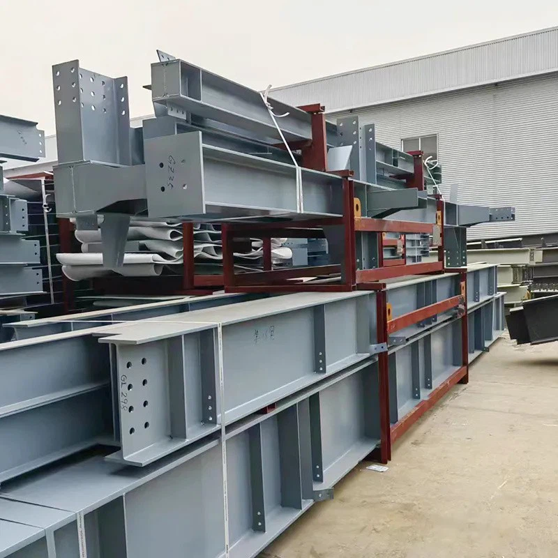
First off, what's an H Beam? You can check out more about them here: H Beam. It's a type of structural steel beam with an "H" shaped cross - section. The horizontal elements are called flanges, and the vertical part is the web. This unique shape gives H Beams excellent strength and load - bearing capabilities, which is why they're widely used in construction, machinery, and other industries.

Now, let's talk about stress distribution. When a load is applied to an H Beam, different parts of the beam experience different levels of stress. There are mainly two types of stress we need to consider: bending stress and shear stress.

Bending Stress
Bending stress is the stress that occurs when the beam is bent. When a load is placed on an H Beam, it causes the beam to curve. The outer fibers of the beam (the top and bottom flanges) experience the maximum bending stress.
The top flange is in compression, which means it's being squeezed. Think of it like when you push down on a spring; the coils get closer together. In the case of the H Beam's top flange, the molecules are pushed closer to each other, creating compressive stress.
On the other hand, the bottom flange is in tension. It's like when you pull on a rubber band; the molecules are being stretched apart. Tensile stress occurs here. The magnitude of the bending stress is proportional to the distance from the neutral axis of the beam. The neutral axis is an imaginary line within the beam where there is no bending stress. In an H Beam, the neutral axis typically passes through the centroid of the cross - section, which is usually near the middle of the web.
The formula for bending stress is $\sigma = \frac{My}{I}$, where $\sigma$ is the bending stress, $M$ is the bending moment (a measure of the bending effect caused by the load), $y$ is the distance from the neutral axis to the point where you're calculating the stress, and $I$ is the moment of inertia of the cross - section. The moment of inertia is a property that describes how the cross - sectional area is distributed around the neutral axis. For an H Beam, the large flanges increase the moment of inertia, which helps to reduce the bending stress for a given bending moment.
Shear Stress
Shear stress, on the other hand, is the stress that occurs when two adjacent parts of the beam slide past each other. In an H Beam, the majority of the shear stress is carried by the web.
The shear stress is not uniformly distributed across the web. It's highest at the neutral axis and decreases towards the top and bottom of the web. The reason for this is related to the way the internal forces are transferred within the beam. When a load is applied, the web has to transfer the shear force from one flange to the other. The neutral axis is where the shear flow is the most concentrated, resulting in the highest shear stress.
The formula for average shear stress in the web is $\tau=\frac{V}{A_{web}}$, where $\tau$ is the shear stress, $V$ is the shear force (the force that causes the parts of the beam to slide relative to each other), and $A_{web}$ is the cross - sectional area of the web. However, this is just an average value, and the actual shear stress distribution is more complex.
Factors Affecting Stress Distribution
Several factors can affect the stress distribution in an H Beam.
- Load Type: The way the load is applied matters a lot. A point load (a single concentrated force) will create a different stress distribution compared to a uniformly distributed load (a load that is spread evenly over a length of the beam). For example, a point load applied at the center of a simply - supported H Beam will cause a high bending moment at the center, resulting in high bending stress in the flanges at that point.
- Support Conditions: How the beam is supported also impacts stress distribution. A simply - supported beam (supported at two ends) will have a different stress pattern compared to a fixed - ended beam (where the ends are fixed and cannot rotate). In a fixed - ended beam, the bending moments are redistributed, and the maximum bending stress may occur at different locations compared to a simply - supported beam.
- Geometry of the H Beam: The dimensions of the flanges and the web play a crucial role. A beam with wider flanges will have a higher moment of inertia, which reduces the bending stress. Similarly, a thicker web can handle higher shear stresses. You can explore different H Beam geometries here: H Steel Beam.
Importance of Understanding Stress Distribution
Understanding the stress distribution in an H Beam is super important. For engineers and architects, it helps in designing structures that can safely carry the intended loads. They can choose the right size and shape of the H Beam based on the expected stress levels.
For us as suppliers, it allows us to provide the best advice to our customers. We can help them select the most suitable H Beams for their projects, ensuring that they get a product that meets their requirements in terms of strength and durability.

If you're in the market for high - quality H Beams and want to learn more about how stress distribution affects your project, don't hesitate to reach out. We're here to assist you in making the right choice for your construction or industrial needs. Whether you're building a small shed or a large commercial building, our H Beams are designed to perform under various stress conditions.
Let's have a chat about your project requirements and find the perfect H Beam solution for you.
References
- Budynas, R. G., & Nisbett, J. K. (2011). Shigley's Mechanical Engineering Design. McGraw - Hill.
- Timoshenko, S. P., & Gere, J. M. (1972). Mechanics of Materials. Van Nostrand Reinhold.